|
Magnetism >>
|
Electricity has become an essential part of our everyday lives. This unit investigates what is required for an electric current to flow around a circuit and how it is measured and varied. The students will learn the difference between the electricity from a battery (dc) and that from the mains (ac). The unit covers electrical safety and the applications and purposes of fuses, circuit breakers and earthing.
|
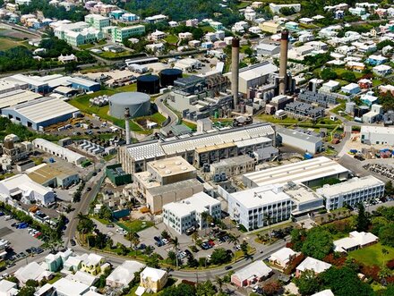
BELCO - Bermuda's electricity generating plant. BELCO runs on a large number of diesel engines and a handful of gas turbine engines. The fuel is imported from Venezuela and Texas.
|
6.1 - Charge, Voltage and Current
- understand that a current is the rate of flow of charge (electrons)
- know and use the relationship between charge, current and time
- understand that the current depends on the applied voltage, which is a measure of the energy supplied to the electrons
- be able to use circuit diagrams
Electricity is the flow of sub-atomic charged particles, known as electrons, around a circuit. If the circuit is broken at any point this flow of electron ceases and the electricity stops. This is the principle that switches use. Students often find the idea that the wires are full of electrons difficult, even if they are not moving. They are the outer electrons of the atoms that make up the conductor, which are loosely attached to their nuclei and are free to hop, skip and jump to their neighbouring atoms, if there is a space available. Therefore, you could imagine that electricity is a flow of hopping electrons... When a voltage is applied, they have the energy that they need to move. The voltage is a measure of the energy supplied to each electron. As the electrons are incredibly tiny, we tend to use a large batch of them so that the total charge of particles equals one coulomb. The higher the voltage, the greater the amount of energy that the electrons have.
- 1 Volt = 1 joule of energy per coulomb of charge (the amount of 'push' that the battery gives).
- 1 Amp = 1 coulomb of charge flowing per second (a measure of how quickly the electrons move)
Both of these variables can be easily measured using a voltmeter and an ammeter respectively. Note: ammeters must be connected in series and the voltmeters in parallel. We say "current through a component" and "voltage across a component".
Series and Parallel circuits. Series circuits have components that follow on from each other (like the episodes in a TV series), while parallel circuits have components that are connected independently of each other (usually drawn on parallel branches). The vast majority of practical circuits are connected in parallel as the components are a) independent of one another and b) have the same voltage across them. The resistance of a series circuit increases with every extra component so the voltage across each is split into smaller chunks. You will be performing a few experiments on the current and voltage in the two circuits.
|
|
|
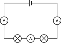
Series circuit - all the current flows along one route. As the voltage from the battery is shared by the bulbs, each is dimmer.
|
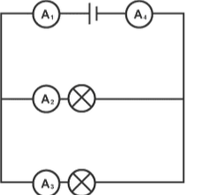
Parallel circuit - there are effectively two separate circuits that carry the current. Where the circuits coincide, the currents are added together. E.g. If both bulbs are carrying 1.5 A of current then both A1 and A4 would read 3.0 A.
|
LAB WORK - you will be spending some time making simple circuits and measuring the current and voltage.
| Click to Run |
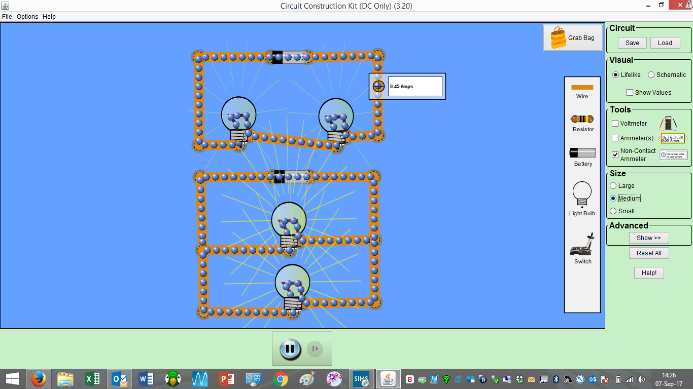
|
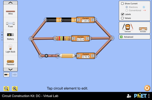
Example of a series and parallel circuit simulation build using the PhET kit. Using the voltmeters and ammeters helps to aid understanding about the properties of the two types of circuit.
|
6.2 - Ohm's Law
- know and use the relationship between voltage, current and resistance
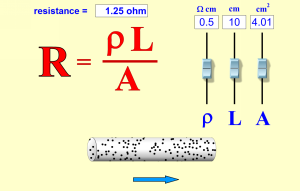
- investigate the variables that affect the resistance of a constantan wire
Remembering that conceptually voltage can be loosely thought of a measure of how much "push" the battery gives the electrons and that current is a measure of how fast the electrons move, it seems clear that the harder you push the electrons, the faster they go! This is essentially the gist of Ohm's Law.
\[V = IR\]
- The current is proportional to the voltage applied.
\[V = IR\]
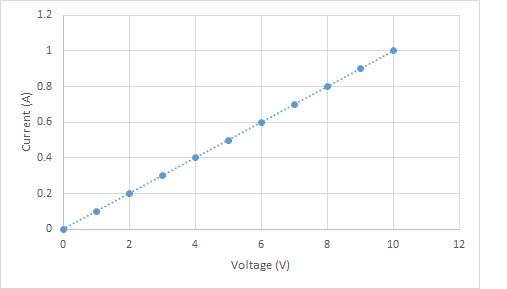
|
Graphical representation of Ohm's Law. Note that the data form a straight (linear) line. This shows that the current (y-axis) is proportional to the voltage (x-axis). As an aside: the current is caused by the voltage, so make sure that you get the cause and effect right in your experimental analysis!
|
LAB WORK - You will be doing a number of experiments to verify Ohm's Law and also to investigate the variables that affect the resistance of a length of wire.
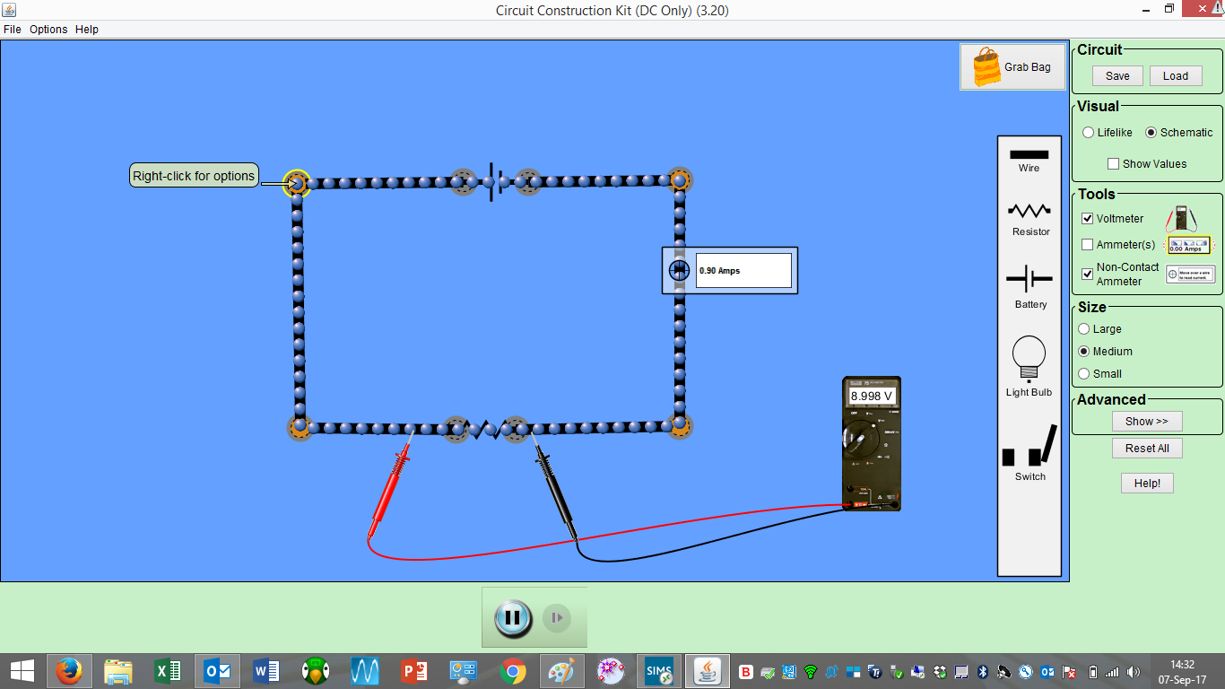
|
Using the PhET Circuit kit to demonstrate Ohm's Law. Note that I used a resistor rather than a light bulb as the component.
|
|
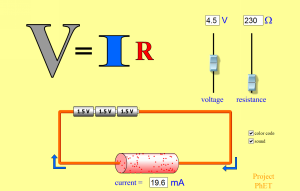
|
PhET Simulations - The above simulations are more to aid with the concepts and also help with the understanding of how the equation works. The second simulation contains an equation that is for AP rather than IGCSE, but should aid in the understanding of the lab on the factors that affect the resistance of a length of wire.
6.3 - Light Bulbs and Other Components
- describe how and why the resistance varies with voltage in a filament lamp
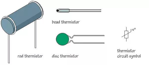
- describe how the resistance and hence current varies in diode, LDR and thermistor
- be able to perform experiments to demonstrate these
|
|
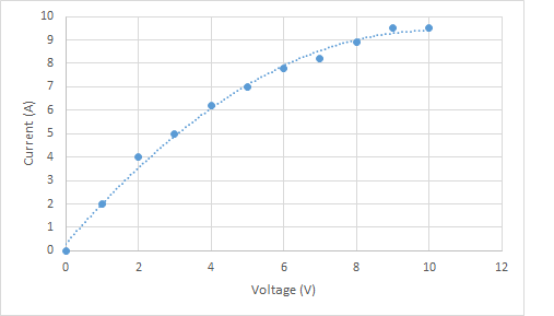
The incandescent light bulb that was invented over 100 years ago by Thomas Edison is a remarkable, if staggeringly inefficient, device. It works on the principle of a current heating up a wire of high resistance to the point that it glows. These filaments can reach temperatures comparable with the surface of the Sun! Oxidation of the tungsten is prevented by filling the glass bulb with low pressure argon gas. The filaments eventually "blow" due to the eventual evaporation (sublimation) of the tungsen. The voltage-current graph is not linear, so the current is NOT proportional to the voltage. we say that the bulb is non-ohmic. The reason for this behaviour is that the resistance of the filament increases as it gets hotter.
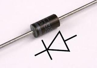
Other non-ohmic components that you know about are: diode (and LED), the light dependent resistor (LDR) and the thermistor. All of these you will be doing lab work on in class.
|
|
|
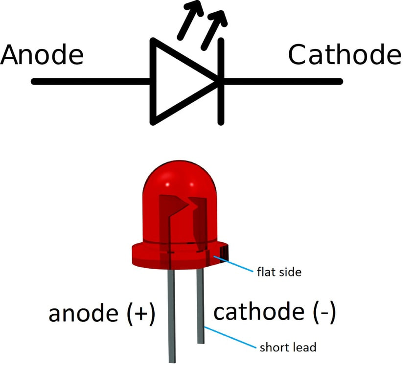
The diode and the light emitting diode (LED) are amazing devices that behave as electrical valves. They only allow the current to flow in one direction. This is one of the reasons why so many devices don't work if you put the batteries in the wrong way around. They are the basis of most electronic circuits. They are also a key component of the rectifier that converts AC electricity to DC electricity. Early LEDs were crude and were found in early clocks and the red/green lights on electronic goods. Recently, LED technology has exploded and now is the lighting of your phone, laptop and TV screens. They also are steadily replacing incandescent and fluorescent light bulbs as they are vastly more efficient.
|
|
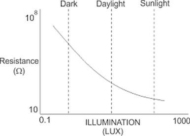
The light dependent resistor (LDR) changes its resistance as the light levels change, As the light gets brighter, the resistance increases. They can be used as light sensors . e.g. for automatic street lighting that turns on at night time and off during the day.
|
|
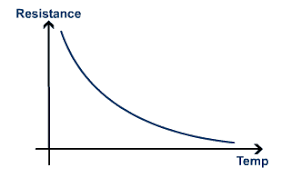
The resistance of a thermistor decreases with temperature. This makes it useful as a electrical temperature sensor for automatic circuits. For example, your fridge. As the temperature increases, the resistance decreases and hence the current through the thermistor increases. This change in current can be measured by the control box and the fridge unit switched on to cool it back down again.
6.4 - Energy and Power
- know and use the relationship between power, current and voltage
- know and use the relationship between energy, current, voltage and time
- be able to calculate the cost of using electrical devices
The energy in a circuit is supplied by the battery and transferred from the battery to the components by the current. The higher the current, the faster the energy is transferred. So it should be obvious that the rate of transfer of energy is the product of both the voltage and the current. From the definitions of voltage (energy per coulomb) and current (charge per unit of time):
\[V = \frac{E}{Q}\]
\[I = \frac{Q}{t}\]
\[P = \frac{E}{t}= \frac{IQV}{Q} = IV\]
It follows that as power is the rate of transferring energy, we can calculate the energy transferred in any given period of time by:
\[E=IVt\]
As an example: I use a \(1.5 \,\text{kW}\) kettle for \(1 \,\text{hour}\) a day to make tea. Over a month that is roughly \(30 \,\text{hours}\). The energy required to boil the water for my tea habit will be:
\[E = 1500 \,\text{W}\times (30 \,\text{hrs}\times 60\times 60)\]
\[E = 162,000,000\,\text{J}\]
Just for a single kettle for a few hours this number is getting very large and difficult to handle. The joule is simply too small a unit for BELCO to use, so they use the kilowatt-hour \(\text{(kWh)}\). The energy supplied to your house is what makes up your BELCO bill. The more energy you use, the more you have to pay. That is the energy as power rating x time in hours. Rather unimaginatively they tend to name this unit as "UNIT"! Bermuda has some of the most expensive electricity in the world at roughly \($0.43\) per \(\text{kWh}\).
To return to my kettle and tea habit:
\[E=Pt\]
\[E = 1.5 \,\text{kW}\times30\,\text{hrs}\]
\[E = 45\,\text{kWh}\]
At a cost of \($0.43\) per unit of electricity, this equates to \($19.35\) per month.
|
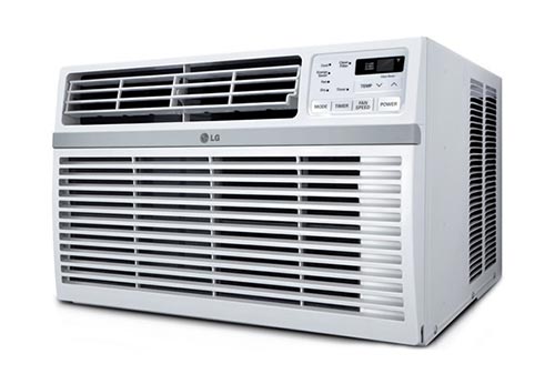
For example: A small window air conditioning unit has a rating of \(1000 \,\text{BTU}\) or \(230 \,\text{W}\) \((0.23 \,\text{kW}\)). If it is used for \(8 \,\text{hours}\) per day for the four summer months a year, the total cost for the electricity will be:
\[E = Pt= 0.23\times \left ( 4\times 30\times 8 \right )= 220.8 \text{kWh}\] \[\text{cost}= \$ 94.94\] |
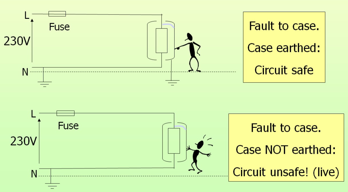
6.5 - Mains Electricity and Electrical Safety
- understand the difference between AC and DC electricity
- understand the hazards of electricity including shock and fire
- know the safety features used to reduce the risks of using electrical devices
Mains electricity is that that is provided by either BELCO or a substitute generator. It has two major differences from the electricity that we have used in class:
- higher voltage (typically \(110 \,\text{V}\) or \(220\text{/}240\,\text{V}\) in the UK)
- AC rather than DC
|
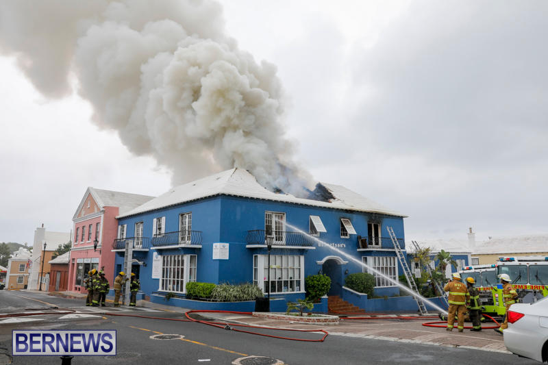
St George's, Bermuda Sept 2017. A fire broke out in the roof space/upper floor area of Robertson's Pharmacy. While the official report has not yet been finished, the working theory is that the fire started in a faulty air con unit. Luckily no-one was injured. Less fortunate was the tragedy in London in July 2017, when a faulty fridge started a fire that ultimately consumed an entire tower block and claimed over 80 lives.
At its most basic level electricity has two main dangers:
|
Since the early days of mains electricity it was realised that the transferring of this form of energy was potentially lethal. Over the years safety devices and systems have been developed to try to avoid both fire and shocks.
Fuses and Circuit Breakers: Designed to prevent the current exceeding a safe level for a specific circuit. The current can exceed a safe level by any of the following:
Fuses and Circuit Breakers: Designed to prevent the current exceeding a safe level for a specific circuit. The current can exceed a safe level by any of the following:
- overloading the circuit by adding too many components
- a short circuit developing due to water, a broken wire/component or incorrect installation
- a power surge (such as when BELCO re-energises their system after a power outage)
|
|
Fuses and circuit breakers come in a wide variety of shapes and sizes.... The max current rating will always be clearly marked on them. You need to have a fuse/circuit breaker that is rated just above the expected current requirement. Too high and it will not prevent a fire, too low and it will constantly cut the current off. If you replace/switch it and it blows/trips straight away, then you clearly have a fault that need attention.
AC/DC
The electricity from lightning, a battery or a solar cell is Direct Current (DC), it only flows in one direction - from positive to negative. This is because the voltage at the positive end is higher than that of the negative terminal of the battery or cell. Everything that uses a battery or has microelectronic chips in it MUST use DC electricity. When Edison first started to electrify New York to make use of his light bulb he quickly ran into a problem. DC electricity can only be transported about a mile before energy losses due to heating in the wires becomes unacceptable. But motors and bulbs worked on DC.
The solution was found by Westinghouse and Tesla. If alternating current that is the natural output from a rotating generator was used it could be stepped up to a high voltage by a transformer and losses due to the high currents would be drastically reduced. Once Tesla had invented an electric motor that could run efficiently on AC, the deal was done. At the moment, AC is the only way to transmit electricity over long distances effectively, because it can be stepped up and down using transformers, unlike DC. The downsides are:
a) AC electricity that has been stepped up to a high voltage is lethally dangerous
b) Any device that has a battery in it needs to have a transformer and rectifier to convert the high voltage AC to low voltage DC. (This is the box that you use to charge your phones/laptops/everything.
|
|
Screencast from PhET Circuit Builder Simulation to show the difference between AC and DC.
The top circuit is DC with a battery. The electrons (and therefore the current) only flow in one direction. The lower circuit is AC with a power supply. The electrons alternate direction. As they move through the bulb it lights up. When they stop to change direction there is no current and the bulb is dark. This is a low frequency AC circuit. In reality the brief pauses where no current flows are too frequent and too brief to see. |
|
|
AddOhms cartoon video explaining the difference between AC and DC.
|
|
|
Extension - Three Phase AC Power. (not on syllabus)
This is a hilarious youtube video made by an electrician who seems to do some rather silly things and shocks himself a lot. Best video that I have seen on three-phase, and also good to demonstrate the dangers of electricity! Warning: DO NOT TRY THIS AT HOME. |
6.6 - Static Electricity
- identify common materials as conductors and insulators
- describe experiments to investigate static electricity
- explain how electrostatic charge is caused by a transfer of electrons
- understand the forces of attraction and repulsion between charges
- explain some of the uses and hazards of static electricity
|
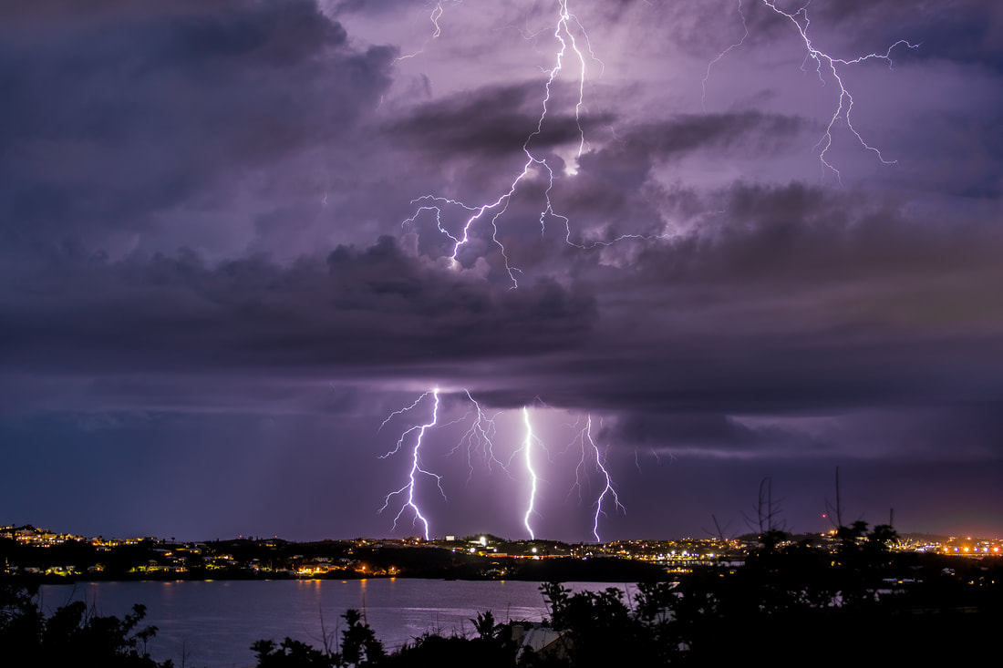
Lightning, Bermuda 2017. (Photo: Adrian Cunningham)
Lightning is a huge spark, caused by an enormous built up static charge in the cloud suddenly going to earth as the voltage exceeds the atmosphere's ability to insulate against it. The sudden flow of charge is effectively a very high (but brief) current that superheats the air and water vapour around the pathway. This superheated air rapidly expands faster than the speed of sound - thus creating the thunder as a sonic boom. The charge is built up by the convection currents carrying ice/water droplets up and down inside the towering cloud. Sparks are a common feature of static electricity and they can and do ignite fuel vapours. Sometimes with lethal effect. |
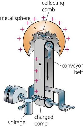
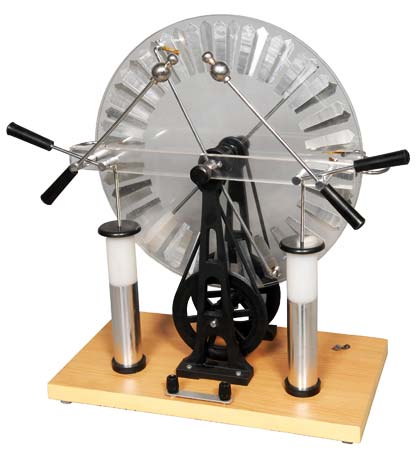
As its name suggests, static electricity is electricity that does not flow. It is often built up on insulating materials due to frictional rubbing. The friction helps to transfer electrons that would not normally move from one place to another. So, one material becomes positively charged as electrons are removed and the other material becomes negatively charged as it gains electrons. Before batteries were invented, scientists produced static electricity for experiments using frictional devices such as the Van deGraff Generator and the wonderfully retro steampunkish Wimshurst Machine. Your teacher will demonstrate these, although they can be very frustrating with Bermuda's high humidity!
|
|
|
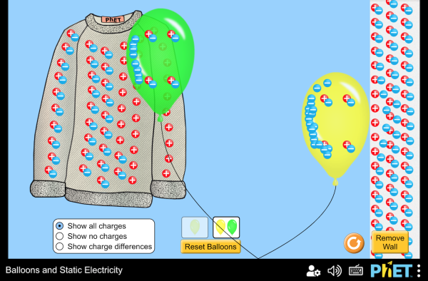
PhET Simulation - Balloons and Static Electricity.
Great little simulation to show the movement of electrons from one insulator to another by friction. Induced charge can be seen when the charged balloon is brought near the wall. |
Other Resources
BBC Bitesize Science - Electricity
Useful website with instructional resources and quizzes.
Useful website with instructional resources and quizzes.
S-COOL revision
Useful website with revision tips and quizzes
Useful website with revision tips and quizzes