During the 19th century, scientists discovered that electricity and magnetism are linked. Since then, the basic concepts of electromagnetism have literally changed the world that we live in. For example: electric motors and large scale electricity generation/transmission, to name just two!
Student booklet - Sept 2021
7.1 - Magnets and Magnetic Fields
- understand that magnets repel and attract other magnets, and attract magnetic substances
- describe the properties of magnetically hard and soft materials and understand that magnetism is induced in some materials when they are placed in a magnetic field
- understand the term ‘magnetic field line’
- describe experiments to investigate the magnetic field pattern for a permanent bar magnet and that between two bar magnets
- describe how to use two permanent magnets to produce a uniform magnetic field pattern
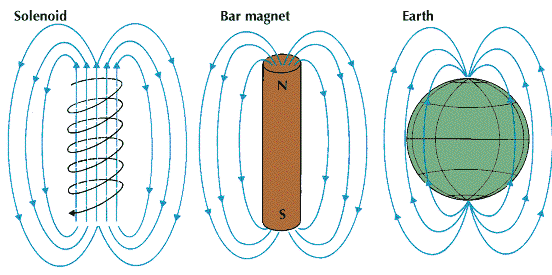
A magnetic field is a region of space around a magnet that a magnetic material, such as iron, experiences a force. They have a characteristic shape that you should learn. The field has a DIRECTION - it goes from the NORTH POLE to the SOUTH POLE. A compass is a small magnet that is balanced on a pivot and allowed to swing. The north pole of a magnet turns to face the North Pole of the Earth - it is a 'north seeking pole'.
|
|
|
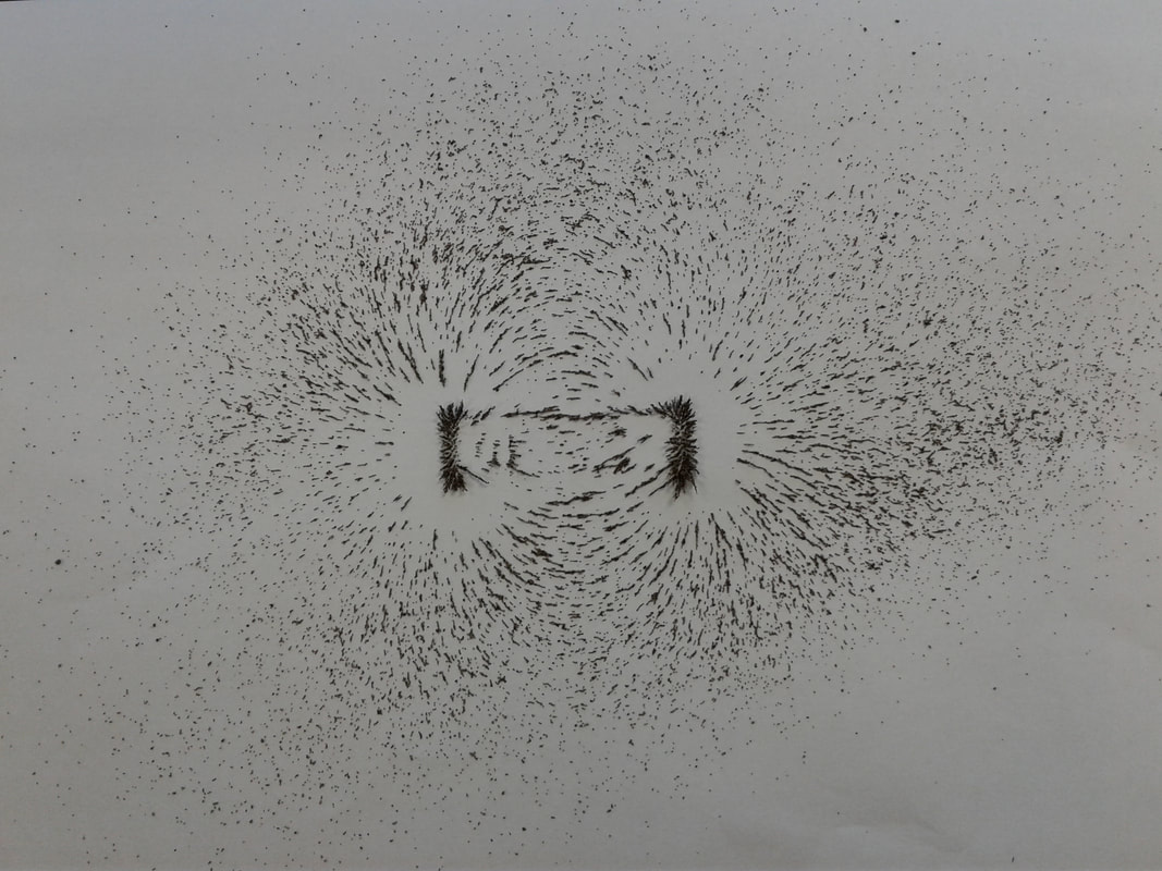
Magnetic field pattern of two opposing magnets. They have been taped to the desk to prevent them moving. Note the lack of a magnetic field between the poles, this is called the NULL POINT.
|
|
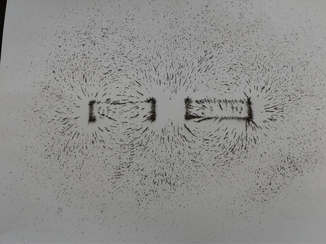
Magnetic field pattern of two attracting magnets. They have been taped to the desk to prevent them moving. Note the strong uniform field between the poles, which almost seems like it is a third magnet in between the other two!
|
|
|
|
|
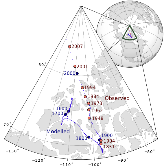
The Earth's Magnetic North Pole - first discovered by James Clarke Ross in 1831 - moves a lot. At the moment it is located in Northern Canada, but appears to be accelerating its motion towards Siberia!
LiveScience article - 14 Jan 2019 |
7.2 - Electromagnetism
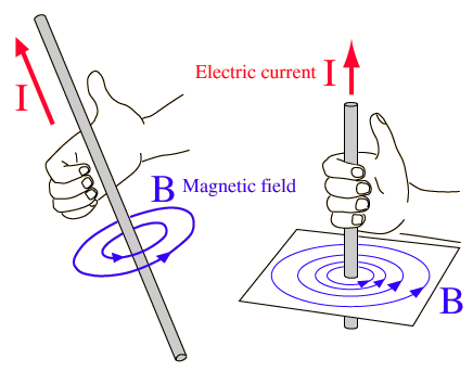
- understand that an electric current in a conductor produces a magnetic field around it
- describe the construction of electromagnets
- sketch and recognise magnetic field patterns for a straight wire, a flat circular coil and a solenoid when each is carrying a current
|
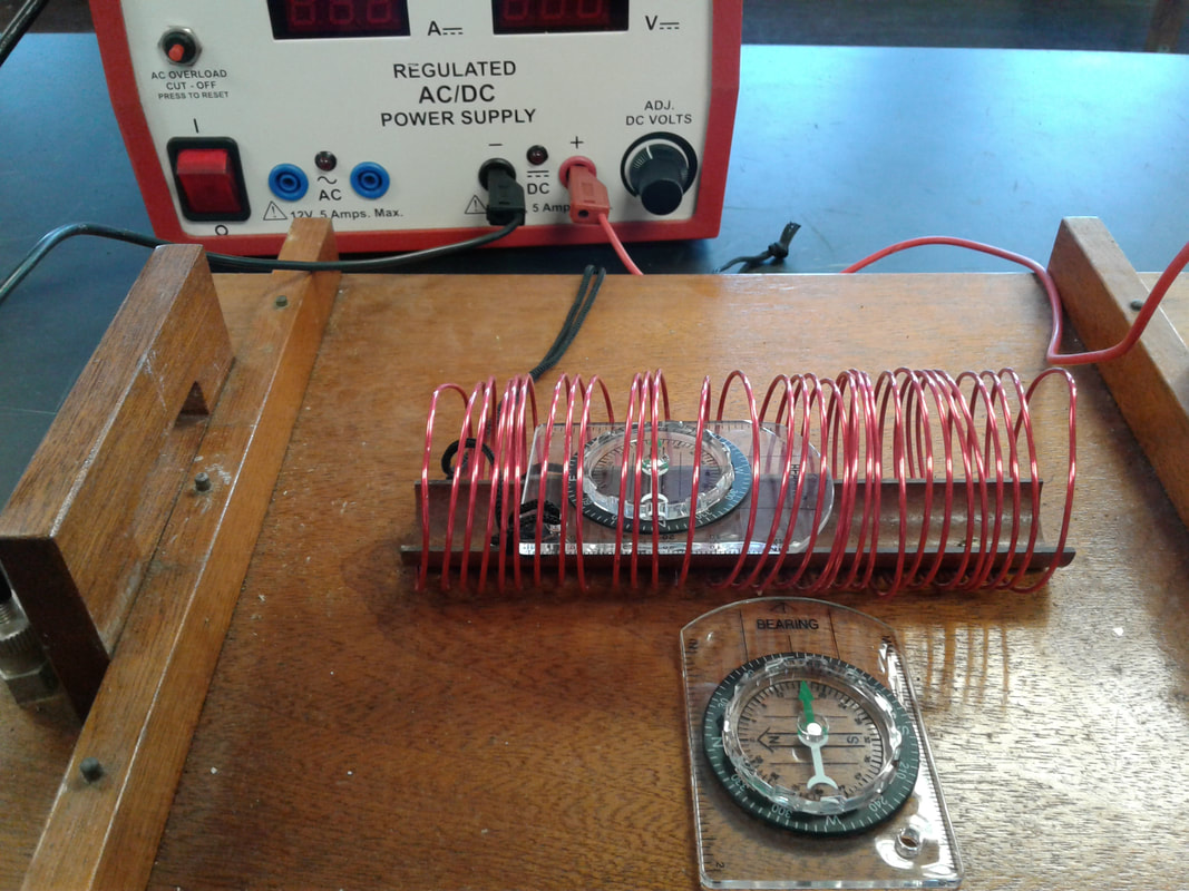
Two compasses and a solenoid (long coil of wire). There is no current and both compasses are pointing north.
|
|
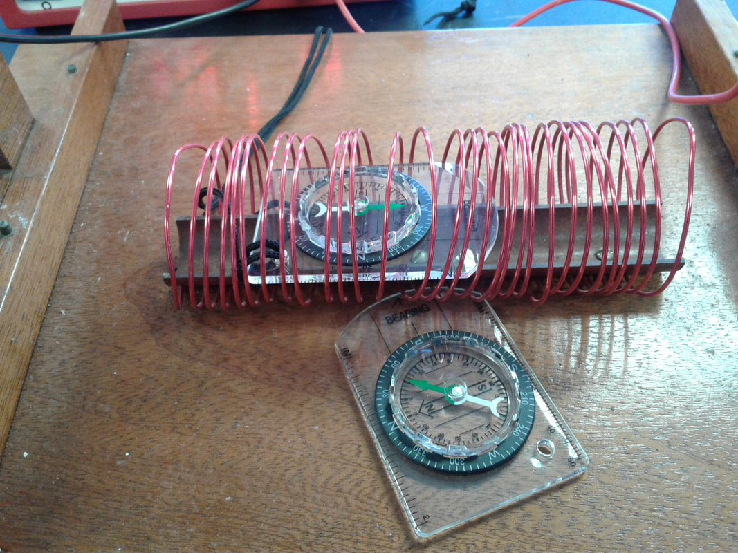
With the current turned on and flowing from left to right, the solenoid has become an electromagnet. The compasses are aligning with the strong local magnetic field instead of that of the Earth. The North Pole of the electromagnet is to the right, The compasses show the field going to the right inside the solenoid and to the left outside. The magnetic field depends on a) the current and b) the number of coils of wire. Adding an iron core will dramatically strengthen the field to a useful amount.
The right hand grip rule can also be used to determine which end of the electromagnet is the north pole. 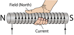
|
7.3 - The Motor Effect
- understand that there is a force on a charged particle when it moves in a magnetic field as long as its motion is not parallel to the field
- understand that a force is exerted on a current-carrying wire in a magnetic field, and, how this effect is applied in loudspeakers and DC motors
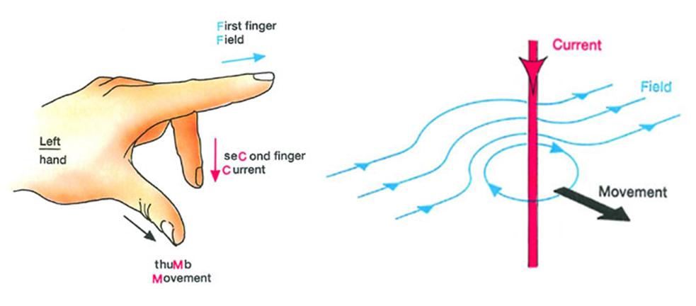
- use the left hand rule to predict the direction of the resulting force when a wire carries a current perpendicular to a magnetic field
|
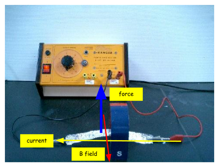
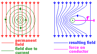
The Motor Effect - the current is flowing through the aluminium foil from right to left, which produces a magnetic field. The permanent magnet produces a magnetic field which is crossing the foil towards the camera. The force due to the interaction of the TWO magnetic fields is mutually perpendicular to the crossed fields and lifts the foil upwards. Almost by magic! Reversing any of the magnetic fields reverses the effect.
|
|
|
Video showing the Motor Effect. At the start the current is flowing away from the camera through the cross bar. The field is going from bottom to top. The direction of the force and hence the motion can be determined by Fleming's Left Hand Rule. When either the current or the field are reversed, the direction of the force is also reversed.
|
So why is the "motor effect" so cool? Easy - it is used wherever you want an electric current to produce motion! Quite literally, the modern world could and would not function without it.
7.4 - Electromagnetic Induction
- Recall that a voltage is induced in a conductor or a coil when it moves through a magnetic field or when a magnetic field changes through it.
- Recall the factors which may affect the size of the induced voltage
- Describe the generation of electricity by the rotation of a magnet within a coil of wire and of a coild of wire within a magnetic field.
Electromagnetic (EM) Induction in my opinion is as close to magic as physics can ever get! The effect is truly amazing and the consequences and applications are widespread. Shortly after Oersted discovered the link between electricity and magnetism and electromagnets were created, Faraday demonstrated that the reverse was true. Magnetism can create electricity. He did this by moving a magnet in and out of a coil of wire. Thus mankind's ability to generate electricity on an industrial scale was born.
The effect is quite small, but can be made stronger by: increasing the strength of the magnet, increasing the number of turns on the coil of wire and increasing the speed of the magnet!
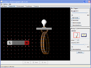
The earliest DYNAMOS were made by spinning a magnet inside a coil of wire. If a commutator was used the output was DC, if not, the output was AC. It was also possible to keep the magnet fixed at the outside and spin the coil of wire instead. Recommend playing with the PhET simulation below....
The effect is quite small, but can be made stronger by: increasing the strength of the magnet, increasing the number of turns on the coil of wire and increasing the speed of the magnet!
The earliest DYNAMOS were made by spinning a magnet inside a coil of wire. If a commutator was used the output was DC, if not, the output was AC. It was also possible to keep the magnet fixed at the outside and spin the coil of wire instead. Recommend playing with the PhET simulation below....
|
PhET - Faraday Lab: This is a great simulation that shows how electricity is generated by rotating a magnet.
|
Of course, it did not take long to realise that if an electromagnet was used, the effect becomes even stronger! But it is not all roses.... It turns out that the law of conservation of energy does not allow us to get something for nothing. In order to get electrical energy out as current x voltage, we must put kinetic energy in. The more current is produced the more effort is required to maintain the speed of the rotation. This was worked out by a Mr Lenz and is known as Lenz's Law. In effect, as the generator turns (say) clockwise to produce a current, that same current creates an electromagnet that tries to counter the rotation. I.e. the dynamo creates a motor that tries to oppose it!
|
Small engine ignition coils
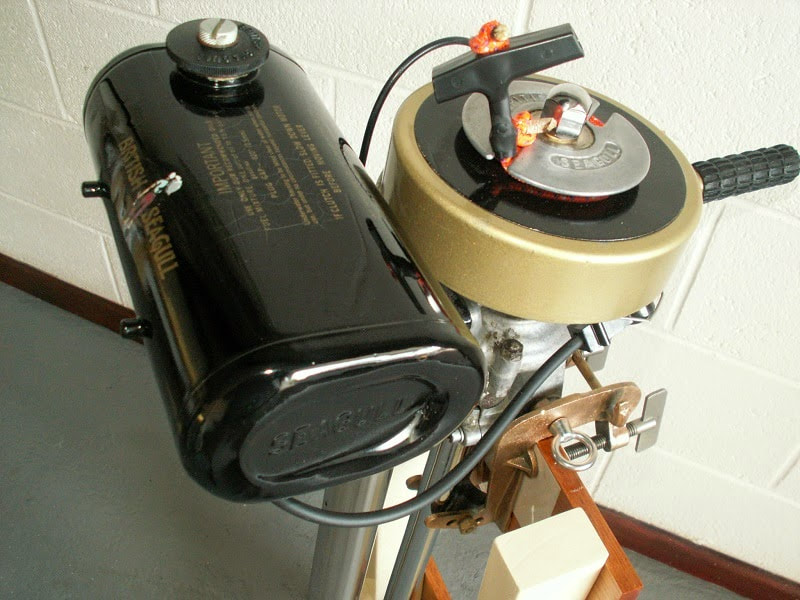
Motor bike, lawnmower and outboard engines use ignition coils to produce the high voltages required for the spark plug. These are often called by an old name - magneto. Essentially there is a lump of iron with a coil of wire around it mounted near the flywheel of the engine. On that flywheel is a magnet. As the operator pulls the cord to spin the flywheel (or uses a starter motor), the motion of the magnet past the coil of wire induces a sudden high voltage in the coil, which is fed directly to the spark plug, creating the spark. If the magnet and coils are set up correctly, this spark occurs just at the point when the piston is at its highest point having compressed the fuel and air mixture and BANG! Engine starts... |
7.5 - Transformers
- Describe the structure of a transformer, and understand that a transformer changes the size of an alternating voltage by having different numbers of turns on the input and output sides.
- Know and use the relationship between input (primary) and output (secondary) voltages and the turns ratio for a transformer.
Transformers are literally everywhere! They change voltages up and down. There is a remarkable lack of consistency in voltages used just in the home alone. Ovens and dryers use \(220 \,\text{V}\), kettles, lamps and toasters use \(110 \,\text{V}\), TVs use \(20 \,\text{V}\), laptops \(19 \,\text{V}\), phones \(3.5 \,\text{V}\) and so on. The way to change the incoming mains voltage to the one we need is by having a transformer. These are usually seen as the 'charging brick' at the plug or on the cable. Sometimes they are built into the device (such as inside the white bit at the bottom of a new LED bulb). They are usually heavyish as they contain a block of iron!
They are the fundamental reason that we use ac electricity for power distribution as we can transmit energy far and wide with minimal losses. (see transmission lines). Transformers range in size from the tiny ones in your phone charger to the massive BELCO substations.
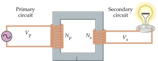
How do they work? Essentially they consist of an ac electromagnet called the 'primary coil' connected to a 'secondary' induction coil.
Primary Coil
The primary coil is connected to an ac voltage. This causes a current to flow around the coil. This creates a magnetic field inside the coil, which is vastly strengthened by inserting a 'soft' iron core. As the current is oscillating at \(60 \,\text{Hz}\), the magnetic field is also oscillating at \(60 \,\text{Hz}\).
Secondary Coil
The core also passes through the secondary coil. As the magnetic field oscillates inside it, a voltage is induced by electromagnetic induction. If the secondary coil is connected to a circuit a current will flow.
Ratios
If the number of turns on each coil were the same, in a perfect world the input and output voltages would be the same. This seems pointless but is sometimes used in isolating transformers - where a waterproof barrier is set between them. The charging stand for an electric toothbrush is a primary coil set in plastic so that water can't get between a connection. The toothbrush is connected - but magnetically! More usefully the ratios of the turns is different to step up or step down the voltages. The number of turns affects the efficiency, the larger the number the more efficient the transformer due to a stronger magnetic field.
The core is usually laminated to reduce 'eddy currents' in the core as the magnetic field swashes back and forth.
They are the fundamental reason that we use ac electricity for power distribution as we can transmit energy far and wide with minimal losses. (see transmission lines). Transformers range in size from the tiny ones in your phone charger to the massive BELCO substations.
How do they work? Essentially they consist of an ac electromagnet called the 'primary coil' connected to a 'secondary' induction coil.
Primary Coil
The primary coil is connected to an ac voltage. This causes a current to flow around the coil. This creates a magnetic field inside the coil, which is vastly strengthened by inserting a 'soft' iron core. As the current is oscillating at \(60 \,\text{Hz}\), the magnetic field is also oscillating at \(60 \,\text{Hz}\).
Secondary Coil
The core also passes through the secondary coil. As the magnetic field oscillates inside it, a voltage is induced by electromagnetic induction. If the secondary coil is connected to a circuit a current will flow.
Ratios
If the number of turns on each coil were the same, in a perfect world the input and output voltages would be the same. This seems pointless but is sometimes used in isolating transformers - where a waterproof barrier is set between them. The charging stand for an electric toothbrush is a primary coil set in plastic so that water can't get between a connection. The toothbrush is connected - but magnetically! More usefully the ratios of the turns is different to step up or step down the voltages. The number of turns affects the efficiency, the larger the number the more efficient the transformer due to a stronger magnetic field.
The core is usually laminated to reduce 'eddy currents' in the core as the magnetic field swashes back and forth.
\[\frac{V_{1}}{V_{2}}=\frac{N_{1}}{N_{2}}\]
As the ratio of the coils equals the ratio of the voltages, the equation is pretty straightforward. Note: we assume \(100\,\precen\) efficiency! However, what happens to the current is of interest as well. The rate of flow of energy into the transformer is determined by the current x voltage. This must be the same out as well as we cannot create or destroy energy. The upshot is that if we increase the voltage out, the current decreases by a corresponding amount. So, if we step up the voltage by a factor of (say) \(20\), the current steps down also by a factor or \(20\). The product of current and voltage remains constant.
\[I_{1}V_{1} = I_{2}V_{2}\]
|
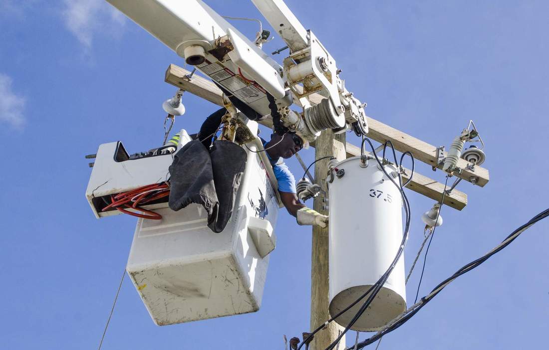
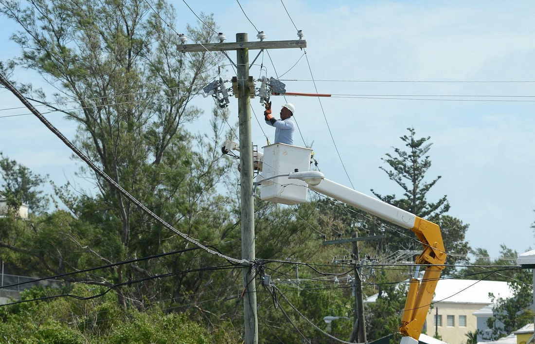
A Belco linesman servicing a distribution transformer. These step down the high voltage on the power line to that which can be used by a house - usually \(110\, \text{V}\). They have circuit breakers on them, which is what he looks like he is working on. During hurricanes and other bad storms, water can sometimes get inside the transformer and they short out with an almighty flash and bang!
|
|
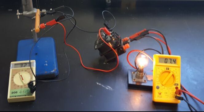
A model transformer. This is a STEP DOWN transformer as the voltage is dropping from 323 V to 7.4 V. The numbers don't quite match the theory due to energy losses - heat and sound. The ratio of the input and output voltages equals that of the two coils.
\[\frac{V_{1}}{V_{2}}=\frac{N_{1}}{N_{2}}\] It is important to note that NO electricity flows through the iron core. Only magnetism. The iron core intensifies the magnetic field that is oscillating due to the ac current in the primary coil. This oscillating magnetic field induces a voltage in the secondary coil. |
7.6 - Transmission Lines
- explain the use of step-up and step-down transformers in the large-scale generation and transmission of electrical energy.
- know use the relationship input power = output power, for 100% efficiency.
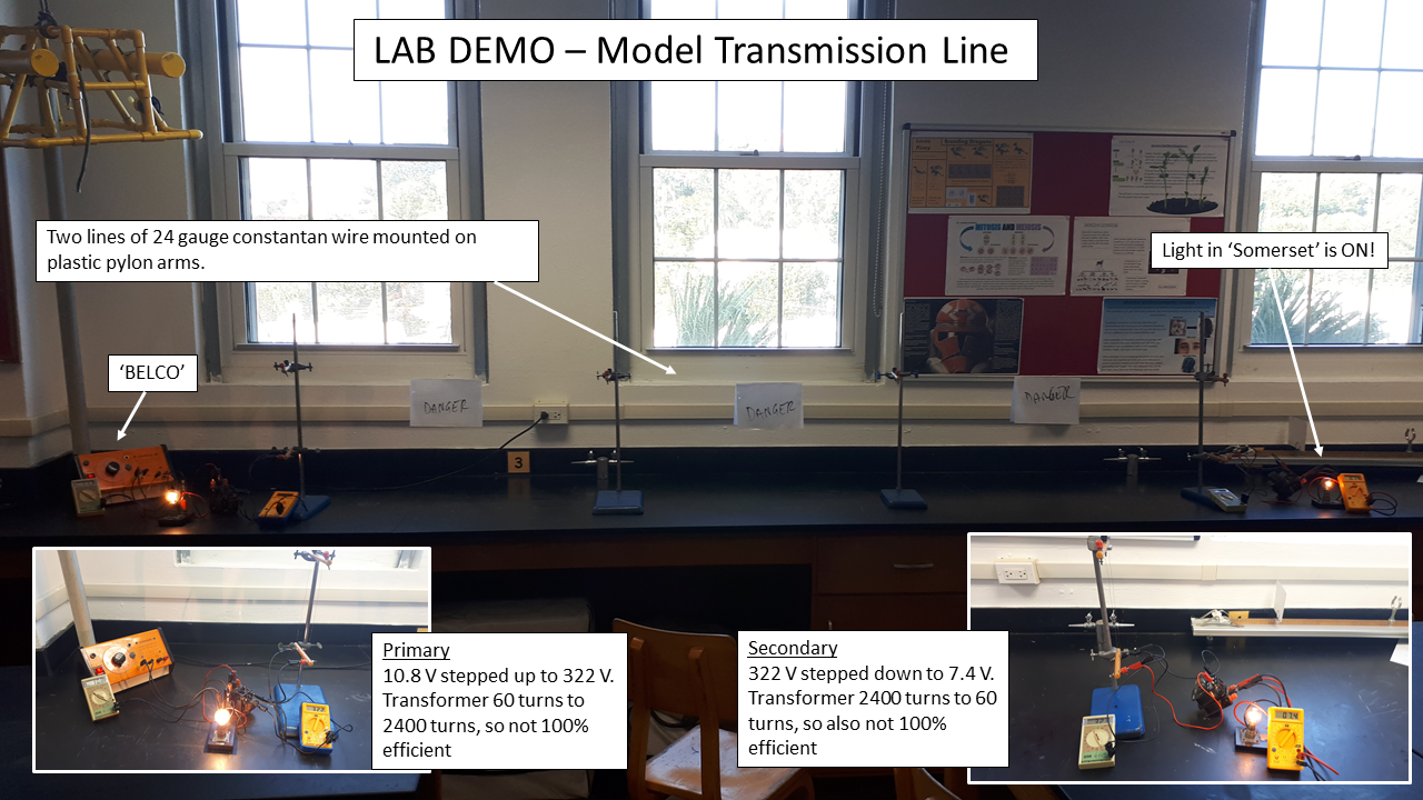
Photo: my model transmission line. First I demonstrate that 10 V directly connected to the line will result in huge power loses. 'Somerset' only receives about 0.7 V, and the lightbulb does not go on. Add the transformers and increase the voltage on the line by 40 times drops the current by a corresponding amount. The power losses are far less - mainly in the crude, and somewhat noisy, transformers.
The problem, as with the real ones, is that the voltage on the lines is dangerously high, (for this demonstration the students are behind another bench to avoid the temptation for 'wandering hands'.)
|
Belco power lines carry electricity from the Pembroke power station around the island at very high voltages. Many of them are at over \(13 \,\text{kV}\). It is lethal to touch them. Every spring, as we are beginning to make our Easter Kites, the company's mascot, the Belco Bird, promotes kite safety. IF your kite gets caught in a power line - DO NOT TOUCH IT! Call Belco on 955.
|

|
Other Resources
|
|
Physics Girl and Credit Cards! After watching this I went up to the chemistry prep room and found some really fine iron filings and tried this. The code shows up just as it did on the video - I was ridiculously excited by this. Didn't try to demagnetise it though as changing card numbers for automatic billing is a royal pain....
|