Since 1844 Gibb's Hill Lighthouse has used a powerful lamp and a rotating Fresnel Lens to cast out a beam to warn mariners of the barrier reef that surrounds the island. (Temporary photo from Getty Images until I get back to the island and take my own....)
7.1 - Reflection
Objectives:
- To understand the law of reflection
- To be able to draw a construction diagram to locate the image produced by a plane mirror.
Light travels in straight line - unless it hits something...
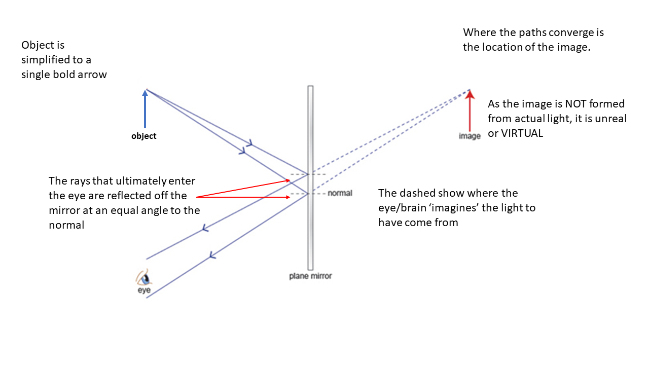
The fundamental concept that the angle of reflection = angle of incidence that you learned during the IGCSE course remains true. We will expand on this to discover how mirrors produce an image. The key point to all of optics is that the brain 'believes' that light travels in a straight line. If its course is changed en route to the eye the brain tends to back track it to where it 'should have' come from. As the image is not made of actual light or substance, we say it is a VIRTUAL image (think not real - virtual reality). On diagrams, lines that represent where we backtrack this imaginary light ray are shown as dashed.
When we look at our reflection, the image is from on the other side of the mirror - it cannot be real. With a plane (flat) mirror the image is the same distance from the reflecting surface as the object is.
7.2 - Curved Mirrors
Objectives:
- To be able to draw a construction diagram to locate and describe the image produced by a spherical mirror, both convex and concave.
- To understand the difference between a real and a virtual image.
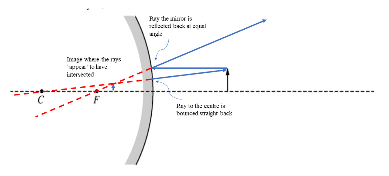
Curved mirrors are very cool. In this unit we only consider spherical mirrors, which have a circular cross section. The centre of curvature is labeled C on the diagrams. The focal point, \(f\), is exactly mid-way between the mirror and the centre of curvature. Note that the radius effectively becomes the normal line. To locate the image produced by a mirror we need to draw a minimum of TWO light rays. The rules are the same for all mirrors, concave and convex.
Also, if the object is located at the focal point, the rays will be parallel - there is no image.
This can also be calculated mathematically. If the distance from the object to the mirror is \(u\), and the distance from the image to the mirror is \(v\), the equation is
\[\frac{1}{f}=\frac{1}{u}+\frac{1}{v}\]
SIGN CONVENTION: Any distance behind a mirror is NEGATIVE. It is usually easiest to sketch the diagram before using the equation.
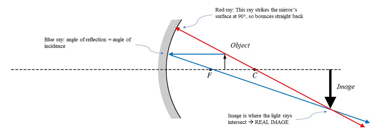
Concave Mirror
- a ray from the top of the object arrow to the mirror that runs parallel to the principal axis of the mirror.
- a ray from the point that the first ray hits the mirror and back through the focal point. (note that if you draw a radius from the centre of curvature to the point on the mirror the angle of incidence and angles of reflections are equal)
- a ray from the top of the object to the mirror and back through the centre of curvature. As the radius is the normal, this represents light being reflected straight back from the mirror.
Also, if the object is located at the focal point, the rays will be parallel - there is no image.
This can also be calculated mathematically. If the distance from the object to the mirror is \(u\), and the distance from the image to the mirror is \(v\), the equation is
\[\frac{1}{f}=\frac{1}{u}+\frac{1}{v}\]
SIGN CONVENTION: Any distance behind a mirror is NEGATIVE. It is usually easiest to sketch the diagram before using the equation.
Concave Mirror
Example calulation based on above diagram. Let \(F = 6\text{ cm}\) and object distance \(u = 8\text{ cm}\). Both values are positive as they are in front of the mirror.
\[\frac{1}{f}=\frac{1}{u}+\frac{1}{v}\]
\[\frac{1}{v}=\frac{1}{f}-\frac{1}{u}\]
\[\frac{1}{v}=\frac{1}{6}-\frac{1}{8}\]
remember to flip the answer...
\[v = 24\text{ cm}\]
The answer is positive, so the image is in front of the mirror. Calculating the magnification of the image is straightforward. The triangles formed by the heights of the arrows and their distances are similar, so the ratios are the same:
\[\frac{h_i}{h_o} = \frac{v}{u}\]
\[magnification = 3\times\]
However, if the object is inside the focal point, the situation is somewhat different.
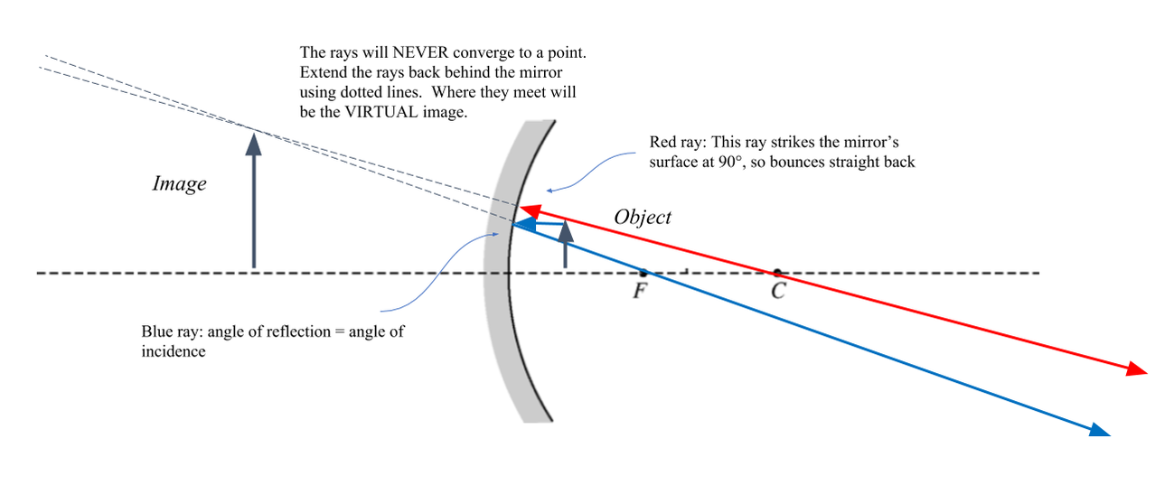
Example calulation based on above diagram. Let \(F = 6\text{ cm}\) and object distance \(u = 2\text{ cm}\). Both values are positive as they are in front of the mirror.
\[\frac{1}{v}=\frac{1}{f}-\frac{1}{u}\]
\[\frac{1}{v}=\frac{1}{6}-\frac{1}{2}\]
this time the answer will be negative. Remember to flip the answer, ...
\[v = -3\text{ cm}\]
The answer is negative, so the image is behind the mirror, i.e. VIRTUAL. Calculating the magnification of the image is the same as above, signs don't matter.
\[\frac{h_i}{h_o} = \frac{v}{u}\]
\[magnification = 1.5\times\]
If the object is located AT the focal point, the image is formed at an infinite distance - i.e. never. This is more usefully used the other way around in satelite dishes and telescopes where parallel light is focused at the focal point. It can also be used if a light source is located at the focal point to produce a parallel beam of light.
|
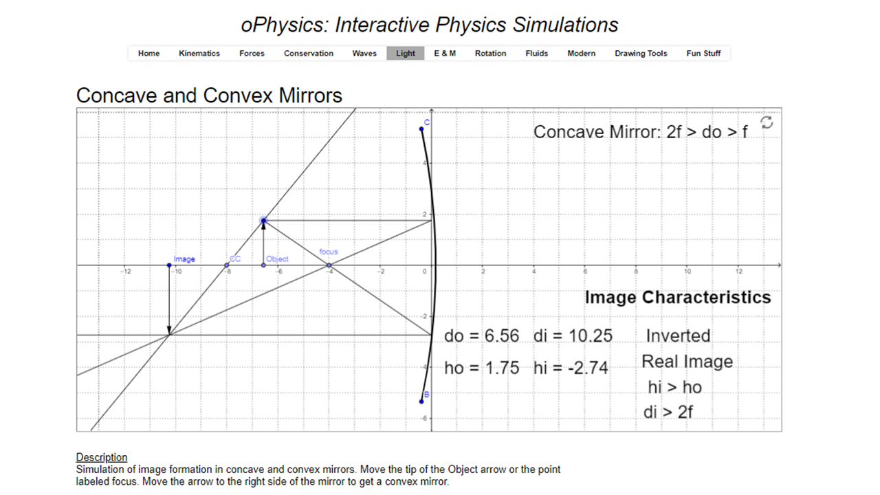
OPhysics - Curved Mirror Virtual Lab
This is a great simulation that can be used to practice calculations. |
Convex Mirrors
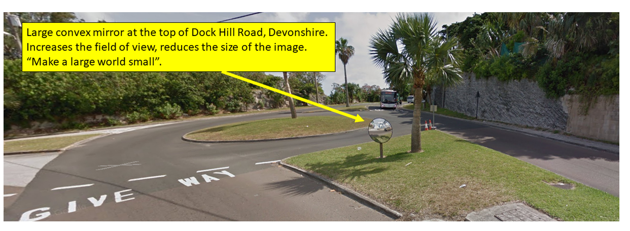
Convex mirrors always produce virtual images that are smaller. "They make the large world smaller". The field of view is increased, which is why they are mounted to the sides of vehicles, blind corners and shops. The equations are exactly the same as the concave mirror. Just remember that the distance from the mirror to the image is negative. Practical idea: use a pencil and a ruler to measure the radius of curvature of the rear view mirror of your motorbike, or a blind corner mirror, if there is one near you.
Convex mirrors always produce virtual images that are smaller. "They make the large world smaller". The field of view is increased, which is why they are mounted to the sides of vehicles, blind corners and shops. The equations are exactly the same as the concave mirror. Just remember that the distance from the mirror to the image is negative. Practical idea: use a pencil and a ruler to measure the radius of curvature of the rear view mirror of your motorbike, or a blind corner mirror, if there is one near you.
Example calulation based on above diagram. Let \(F = -6\text{ cm}\) and object distance \(u = 8\text{ cm}\). The focal length is negative as it is BEHIND the mirror.
\[\frac{1}{f}=\frac{1}{u}+\frac{1}{v}\]
\[\frac{1}{v}=\frac{1}{f}-\frac{1}{u}\]
\[\frac{1}{v}=-\frac{1}{6}-\frac{1}{8}\]
remember to flip the answer...
\[v = -3.4\text{ cm}\]
The answer is negative, so the image is behind the mirror and so is virtual.
\[\frac{h_i}{h_o} = \frac{v}{u}\]
\[magnification = 0.43\times\], so smaller.
7.3 - Refraction
Objectives:
- To understand that light changes it speed and hence its wavelength and bends as it passes from one transparent medium to another.
- To understand and be able to use Snell’s Law for refraction.
Light travels in straight line - unless it changes the medium that it is traveling through...
Refraction occurs when light enters of leaves another transparent medium (air, water, glass, plastic or diamond). The effect of this is that its path changes. It bends. The important bits are a) why, b) how much and c) what are the consequences?
When light moves into a different medium, its speed changes. Its speed is fastest in a vacuum, where the speed of light is \(c = 3.0 \times 10^8 \text{ m/s}\). The factor that it changes is the refractive index. \(n=1.0\) in a vacuum, so the refractive index value will always be \( n \geq 1.0\).
\[n_{1}v_{1}=n_{2}v_{2}\] As the FREQUENCY stays constant as the wave passes from one medium to another, and using the wave equation \(v = f\lambda\), we get:
\[f = \frac{v_1}{\lambda_1}=\frac{v_2}{\lambda_2}\]
What this implies is that as the wave speed decreases as it enters a more dense medium, its wavelength also decreases. One way to visualise this is to imagine a bunch of students walking towards a sandy beach at a constant speed and separated by, say, \(1 \,\text{m}\). As the lead student reaches the sand and slows down, the student behind effectively catches up with him. As they moves slower through the sand, they are closer together. The practical consequence of this is that if the angle of incidence is anything other than zero degrees, its course will be altered. This is refraction. Using the sand analogy, imagine an array of students walking at an angle to the sand, as they intersect in batches, the overall angle changes.
The equation is called Snell's Law:
\[n_{1}\sin{\theta_{1}}=n_{2}\sin{\theta_{2}}\]
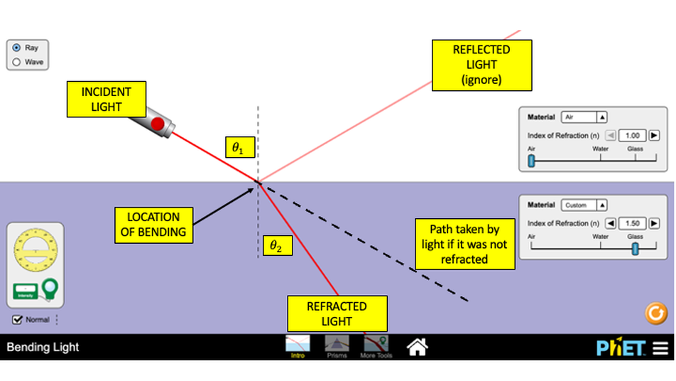
Diagram showing the refraction (bending) of light going from air to glass. Based on a screenshot from the PhET Bending Light simulation.
|
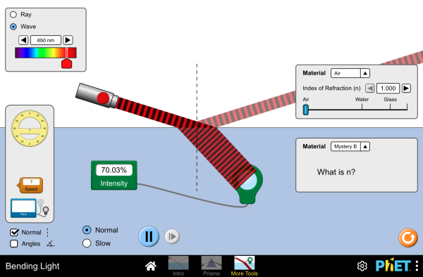
PhET - Bending Light. Probably the best refraction simulation around. For AP you can ignore the reflected ray. The refractive index actually varies with the wavelength. Change the colour of the light and see the effect that it has on the refracted ray of light.
|
|
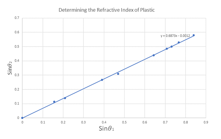
Sample results are shown opposite Students shone a light ray into a demi-circular plastic block at a range of angles. When the sines of the measured angles are plotted, the reciprocal of the gradient yields the refractive index of the plastic (we assumed the the refractive index of air = \(1\)). \(n = 1.45\)
|
|
Puzzle: New York and Chicago are \(1170 \,\text{km}\) apart. There is a fibre optic link between them with a refractive index of \(1.44\). There is also a satellite in orbit above at an altitude of \(550 \,\text{km}\). Assuming that the satellite is exactly midway between the cities and there are no other communication delays in the electronics - which route provides the fastest data link?
7.4 - Lenses
Objectives:
- To be able to draw accurate ray diagrams for both concave and convex spherical lenses.
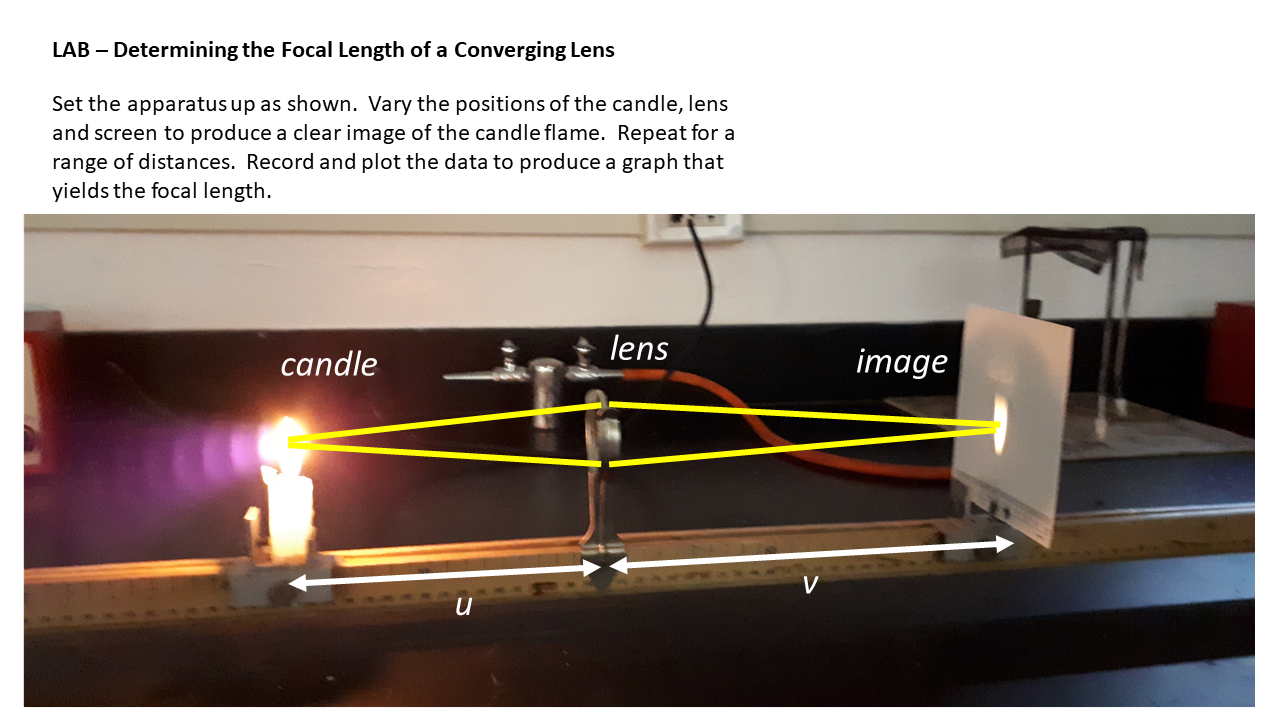
- To be able to calculate the image or object positions using the lens equation (lab work).
- To be able to determine the magnification of the lens.
Very conveniently, the lens equation is identical to the mirror equation:
\[\frac{1}{f}=\frac{1}{u}+\frac{1}{v}\]
\[\frac{1}{f}=\frac{1}{u}+\frac{1}{v}\]
|
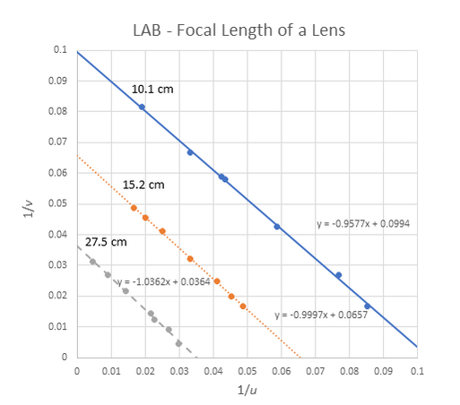
Opposite - results from Jackson's, Cormac's and Max's experiment above on determining the focal lengths of a variety of convex lenses.
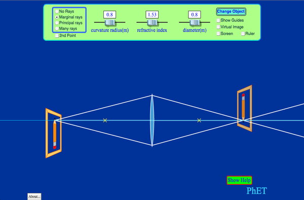
PhET simulation on convex lenses - crude but effective!
|
|
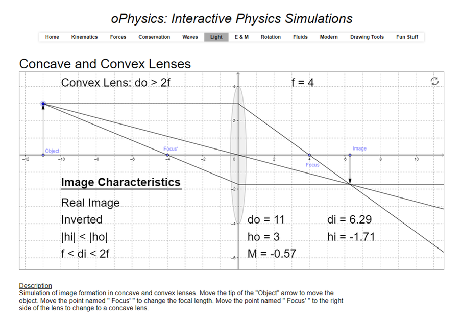
oPhysics - Lenses Simulator
Another great numerical simulation from OPhysics. Note that it uses \(d_o\) and \(d_i\) for the object and image distances. |
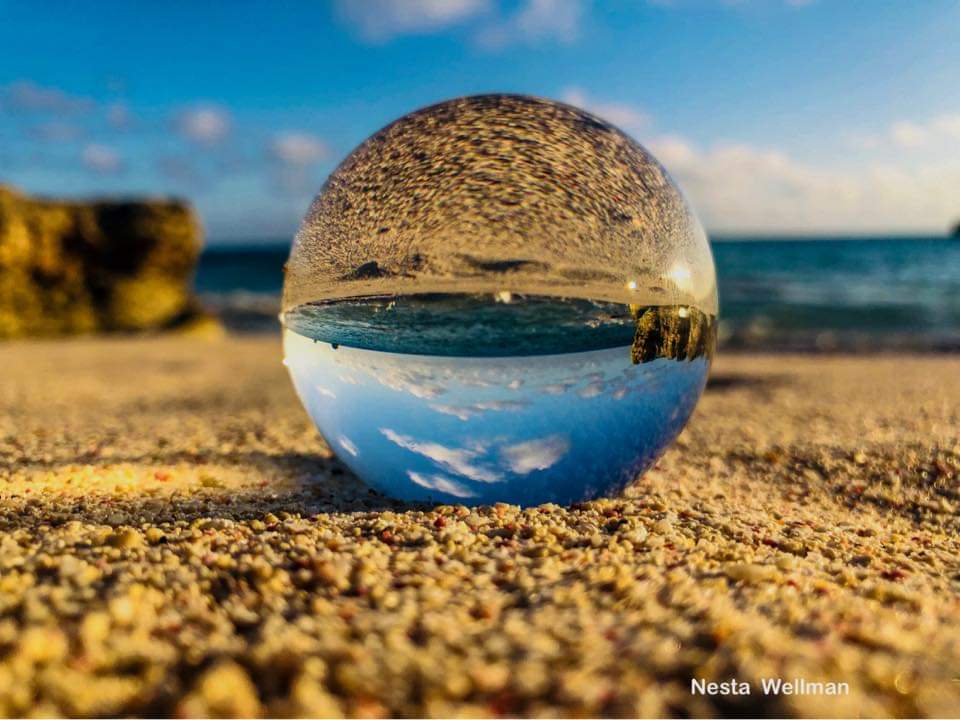
Challenge - explain this! (Photo by young Bermudian aquarist, Nesta Wellman)
|
A glass ball can be used to produce some great photos. This is an example taken by a student on a Bermuda beach. Can you understand why the image is inverted and reduced?
|
7.6 - Total Internal Reflection and Thin Film Interference
Objectives:
- To understand why total internal reflection occurs.
- To be able to calculate the critical angle.
- To describe some of the applications and consequences of the effect.
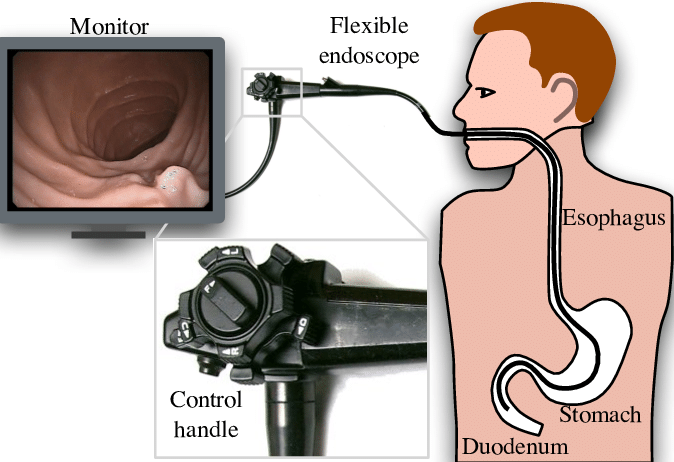
An important consequence of refraction is known as 'total internal reflection'. It occurs when the light speeds up as it leaves an optically dense medium (e.g. glass) and into an optically less dense medium (e.g. air). The angle of refraction is greater than the angle of incidence. It is possible that the angle of refraction exceeds \(90^{\circ}\), in which case it is reflected back into the more dense medium. As all of the light is reflected inside of the material, it is known as total internal reflection. The usefulness of this effect cannot be overstated. It is the fundamental principle behind the fibre optical cables that are used to transmit data signals under the oceans and used by doctors to see inside the body. In Bermuda, it can be seen when snorkeling or diving. There is an angle where the surface of the sea or a divemask appears to turn to a silver mirror!
Optics can give us some spectacular illusions and images.
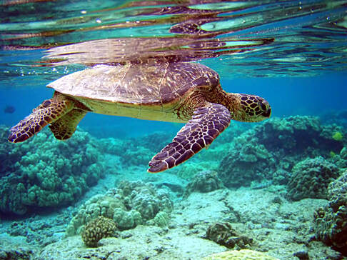
Turtle and total internal reflection.
|
Total internal reflection can be seen on the water's surface just above the turtle swimming over one of Bermuda's reefs. The angle of the observer is important. If you looked directly upwards you would just see straight through the surface.
|
The maths behind calculating the CRITICAL ANGLE for TIR is based on setting the refracted angle to \(90^{\circ}\).
\[n_{1}\sin{\theta_{1}}=n_{2}\sin{\theta_{2}}\]
\[n_{1}\sin{c}=n_{2}\sin{90^{\circ}}\]
\[\sin{c} =\frac{n_2}{n_1}\]
If the less dense medium is air, this further simplifies to:
\[\sin{c} = \frac{1}{n_1}\]
\[n_{1}\sin{\theta_{1}}=n_{2}\sin{\theta_{2}}\]
\[n_{1}\sin{c}=n_{2}\sin{90^{\circ}}\]
\[\sin{c} =\frac{n_2}{n_1}\]
If the less dense medium is air, this further simplifies to:
\[\sin{c} = \frac{1}{n_1}\]
Other Resources
|
|
Second half of a lecture on optics (ray diagrams) given online at Bermuda College during the Coronavirus lockdown.
(this was my first attempt at recording an online lesson.....) |